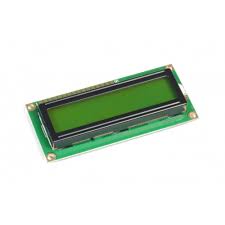
16×2 LCD:
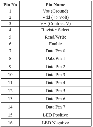
Pin configuration of 16×2 LCD:
Raspberry Pi:
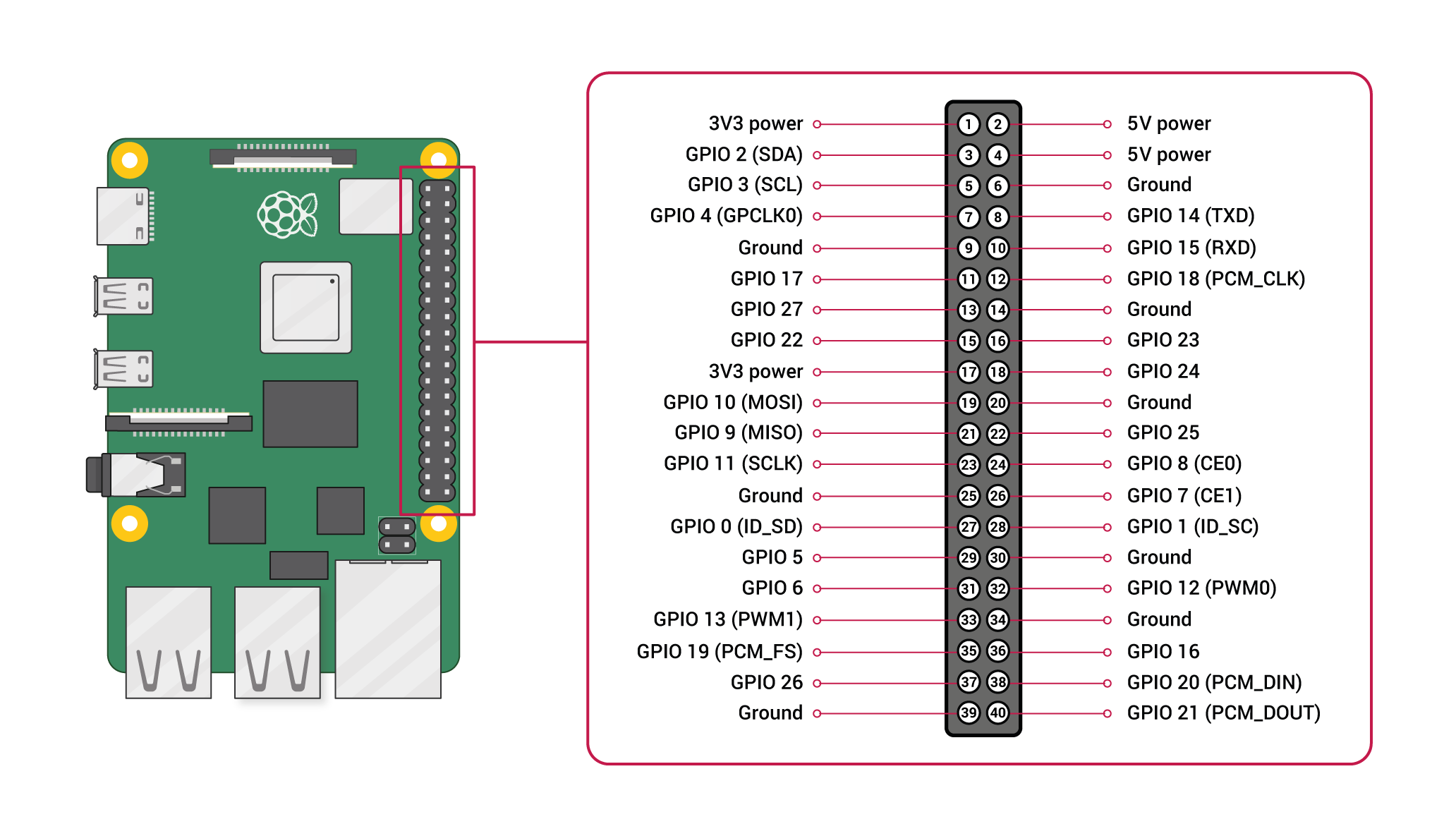
Pin configuration:
1. Vin: Two 5v pins and two 3v3 pins used for providing power supply, where processor works on 3.3v.
Hardware Needed:
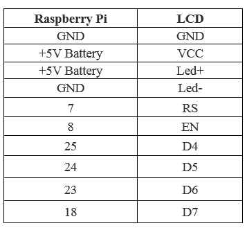
16*2 LCD Display and Raspberry pi pin connections:

import RPi.GPIO as GPIO
from time import sleep

# Define GPIO to LCD mapping
LCD_RS = 7
LCD_E  = 8
LCD_D4 = 25
LCD_D5 = 24
LCD_D6 = 23
LCD_D7 = 18

# Define some device constants
LCD_WIDTH = 16    # Maximum characters per line
LCD_CHR = True
LCD_CMD = False

LCD_LINE_1 = 0x80 # LCD RAM address for the 1st line
LCD_LINE_2 = 0xC0 # LCD RAM address for the 2nd line

# Timing constants
E_PULSE = 0.0005
E_DELAY = 0.0005

def main():
  # Main program block
  GPIO.setwarnings(False)
  GPIO.setmode(GPIO.BCM)       # Use BCM GPIO numbers
  GPIO.setup(LCD_E, GPIO.OUT)  # E
  GPIO.setup(LCD_RS, GPIO.OUT) # RS
  GPIO.setup(LCD_D4, GPIO.OUT) # DB4
  GPIO.setup(LCD_D5, GPIO.OUT) # DB5
  GPIO.setup(LCD_D6, GPIO.OUT) # DB6
  GPIO.setup(LCD_D7, GPIO.OUT) # DB7

  # Initialise display
  lcd_init()

  while True:

    # Send some test
    lcd_string("Gemicates Labs",LCD_LINE_1)
    lcd_string("    Presents    ",LCD_LINE_2)

    sleep(3) # 3 second delay

    # Send some text
    lcd_string("Rasbperry Pi",LCD_LINE_1)
    lcd_string("16x2 LCD Test",LCD_LINE_2)
    sleep(3)

def lcd_init():
  lcd_display(0x28,LCD_CMD) # Selecting 4 - bit mode with two rows
  lcd_display(0x0C,LCD_CMD) # Display On,Cursor Off, Blink Off
  lcd_display(0x01,LCD_CMD) # Clear display

  sleep(E_DELAY)

def lcd_display(bits, mode):
  # Send byte to data pins
  # bits = data
  # mode = True  for character
  #        False for command

  GPIO.output(LCD_RS, mode) # RS

  # High bits
  GPIO.output(LCD_D4, False)
  GPIO.output(LCD_D5, False)
  GPIO.output(LCD_D6, False)
  GPIO.output(LCD_D7, False)
  if bits&0x10==0x10:
    GPIO.output(LCD_D4, True)
  if bits&0x20==0x20:
    GPIO.output(LCD_D5, True)
  if bits&0x40==0x40:
    GPIO.output(LCD_D6, True)
  if bits&0x80==0x80:
    GPIO.output(LCD_D7, True)

  # Toggle 'Enable' pin
  lcd_toggle_enable()

  # Low bits
  GPIO.output(LCD_D4, False)
  GPIO.output(LCD_D5, False)
  GPIO.output(LCD_D6, False)
  GPIO.output(LCD_D7, False)
  if bits&0x01==0x01:
    GPIO.output(LCD_D4, True)
  if bits&0x02==0x02:
    GPIO.output(LCD_D5, True)
  if bits&0x04==0x04:
    GPIO.output(LCD_D6, True)
  if bits&0x08==0x08:
    GPIO.output(LCD_D7, True)

  # Toggle 'Enable' pin
  lcd_toggle_enable()

def lcd_toggle_enable():
  # Toggle enable
  time.sleep(E_DELAY)
  GPIO.output(LCD_E, True)
  time.sleep(E_PULSE)
  GPIO.output(LCD_E, False)
  time.sleep(E_DELAY)

def lcd_string(message,line):
  # Send string to display

  message = message.ljust(LCD_WIDTH," ")

  lcd_display(line, LCD_CMD)

  for i in range(LCD_WIDTH):
    lcd_display(ord(message[i]),LCD_CHR)

if __name__ == '__main__':

  try:
    main()
  except KeyboardInterrupt:
    pass
  finally:
    lcd_display(0x01, LCD_CMD)
    GPIO.cleanup()